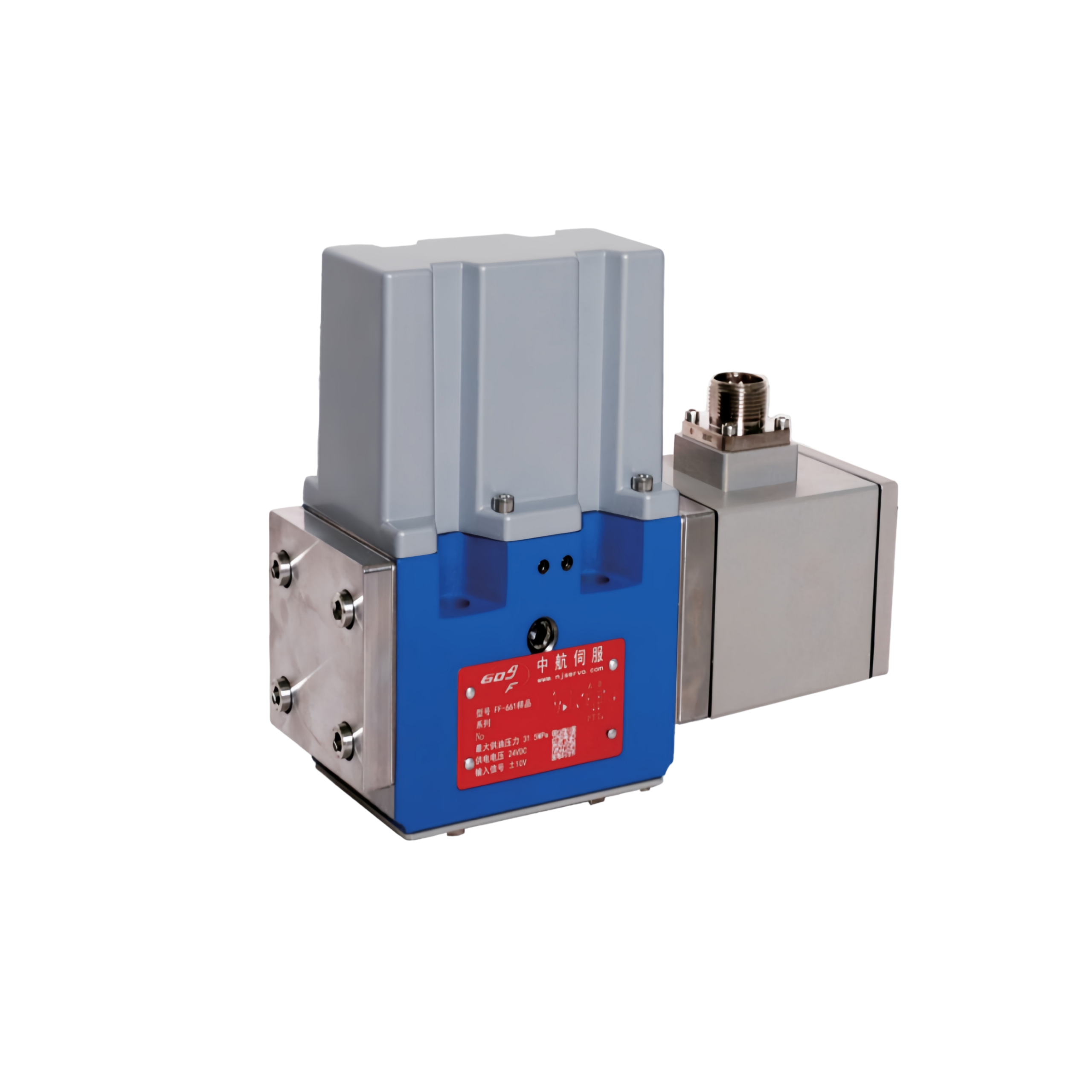
FF-661 Electro-Hydraulic Servo Valve Overview
The FF-661 series electro-hydraulic servo valve is a two-stage, jet-pipe type proportional flow control servo valve with internal LVDT (Linear Variable Differential Transformer) electrical spool position feedback. Supplied globally by Huafilter as a direct, cost-effective drop-in replacement for the Moog D661 series, the FF-661 is manufactured by AVIC Nanjing Servo Control System Co., Ltd.—an independent precision servo enterprise spun off from the Hydraulic Servo Division of the Jincheng Nanjing Electromechanical Hydraulic Engineering Research Center (AVIC No. 609 Research Institute, specialty founded in 1961).
Designed for closed-loop industrial motion, pressure, and force control, the FF-661 delivers a rated flow range of 8 L/min to 80 L/min at a 1 MPa (10 bar / 145 PSI) valve pressure drop. Its high-flow jet-pipe pilot stage provides superior contamination tolerance compared to conventional nozzle-flapper designs, while internal or external pilot supply options, an external electrical zero-adjustment mechanism, and customizable fail-safe spool positioning upon electrical or hydraulic power loss ensure reliable operation in metallurgy, chemical engineering, mechanical manufacturing, geological exploration, power systems, and dynamic test rigs.
FF-661 and Moog D661 Interchangeability Attributes
The FF-661 series aligns with the mounting interface, operating pressure envelope, and closed-loop electrical feedback architecture of the Moog D661 servo valve family. Engineering procurement teams can evaluate direct functional compatibility across the following core attributes.
| Attribute Dimension | FF-661 Series Specification | Moog D661 Series Reference | Engineering Compatibility Note |
|---|---|---|---|
| Pilot Stage Architecture | Two-stage jet-pipe pilot stage | Two-stage jet-pipe / servo-jet pilot stage | High contamination resistance and low null-shift sensitivity |
| Feedback Mechanism | Internal LVDT closed-loop spool position feedback | Internal LVDT spool position transducer | Low hysteresis, high resolution, and consistent repeatability |
| Rated Flow Range (Δp = 1 MPa / 10 bar) | 8 L/min to 80 L/min | Comparable nominal flow ratings | Direct flow curve matching across standard industrial sizing |
| Max. Operating Pressure (P, A, B) | ≤ 35 MPa (350 bar / 5,076 PSI) | 35 MPa (350 bar / 5,000 PSI) | Full high-pressure parity for heavy industrial circuits |
| Pilot Supply & Return Options | Internal or external X / Y configuration | Internal or external pilot supply / drain | Configurable to match existing manifold porting |
| Fail-Safe Function | Customizable safe spool position on power/pressure loss | Fail-safe spring-centered or defined end-position | Supports safe actuator shutdown during emergency stops |
Technical Specifications of FF-661 Servo Valve
The following engineering specifications define the hydraulic operating limits, fluid cleanliness requirements, environmental tolerances, and physical characteristics of the FF-661 servo valve.
| Parameter | Specification |
|---|---|
| Rated Flow Range | 8 L/min to 80 L/min at Δp = 1 MPa (10 bar / 145 PSI) |
| Working Pressure (Ports P, A, B) | ≤ 35 MPa (350 bar / 5,076 PSI) |
| Working Pressure (Ports T, T2 — Internal Y) | ≤ 21 MPa (210 bar / 3,045 PSI) |
| Working Pressure (Ports T, T2 — External Y) | ≤ 35 MPa (350 bar / 5,076 PSI) |
| Ambient Temperature Range | -20 °C to +60 °C (-4 °F to +140 °F) |
| Fluid Temperature Range | -20 °C to +80 °C (-4 °F to +176 °F) |
| Sealing Materials | NBR (Nitrile rubber) or FKM (Fluororubber / Viton); custom seals available upon request |
| Working Medium | Petroleum-based hydraulic oil complying with DIN 51524 (10–400 mm²/s at 38 °C); consult engineering for special fluids |
| Recommended Fluid Viscosity | 15 mm²/s to 100 mm²/s (cSt) |
| Permissible Fluid Viscosity | 5 mm²/s to 400 mm²/s (cSt) |
| Cleanliness Class (Standard Operation) | NAS 1638 Class 7 / ISO 4406 19/16/13 / GB/T 14039-2002 19/16/13 / GJB 420B Class 7 |
| Cleanliness Class (Long-Life Operation) | NAS 1638 Class 5 / ISO 4406 17/14/11 / GB/T 14039-2002 17/14/11 / GJB 420B Class 5 |
| Filtration Precision | Standard: β₁₀ ≥ 75 (10 μm absolute) / Long-life: β₃ ≥ 75 (3 μm absolute) |
| System Filtering Requirement | High-pressure inline filter without bypass and with clogging indicator installed close to valve inlet; external circulation filter recommended for fast-response variable pumps |
| Vibration Resistance | 30 g, triaxial, 5 Hz to 2 kHz |
| Weight | 5.7 kg (12.57 lbs) |
| Protective Base Plate | Included upon shipment to protect precision lapped mounting face |
Key Performance Features and Jet-Pipe Working Principle
The FF-661 integrates a torque-motor-driven jet-pipe pilot stage with a high-force main spool stage to achieve fast dynamic response and stable static resolution.
- Jet-Pipe Pilot Stage — Tolerates higher fluid contamination levels than small-orifice flapper valves, reducing silt-induced null shift.
- Flexible Pilot Configuration — Pilot stage supply and return ports can be configured for internal or external operation.
- External Electrical Zero Adjustment — Simplifies on-site null calibration directly on the integrated control housing.
- Two-Stage Spool Actuation — Provides high driving force on the main spool to overcome Bernoulli flow forces and friction.
- High Dynamic Response and Static Linearity — Delivers low hysteresis, high resolution, and repeatable closed-loop control.
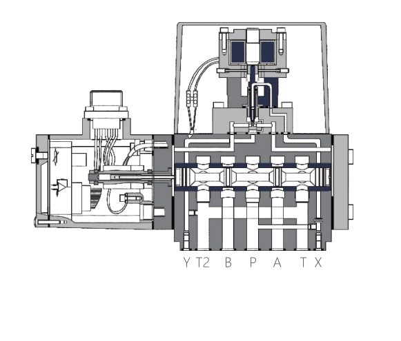
When an input command signal is applied, the integrated controller inside the servo valve generates a control current supplied to the torque motor coil. This current produces an electromagnetic torque that deflects the jet pipe, creating a control pressure differential across the ends of the main valve spool and driving the spool to shift. An internal LVDT (Linear Variable Differential Transformer) displacement sensor mounted on the spool generates a position feedback signal that is returned to the integrated controller and compared against the input command signal. The resulting error signal is amplified to drive the pilot stage until the error reaches zero. Consequently, main spool stroke remains directly proportional to the input command signal, producing a linear, proportional output flow within the rated operating envelope.
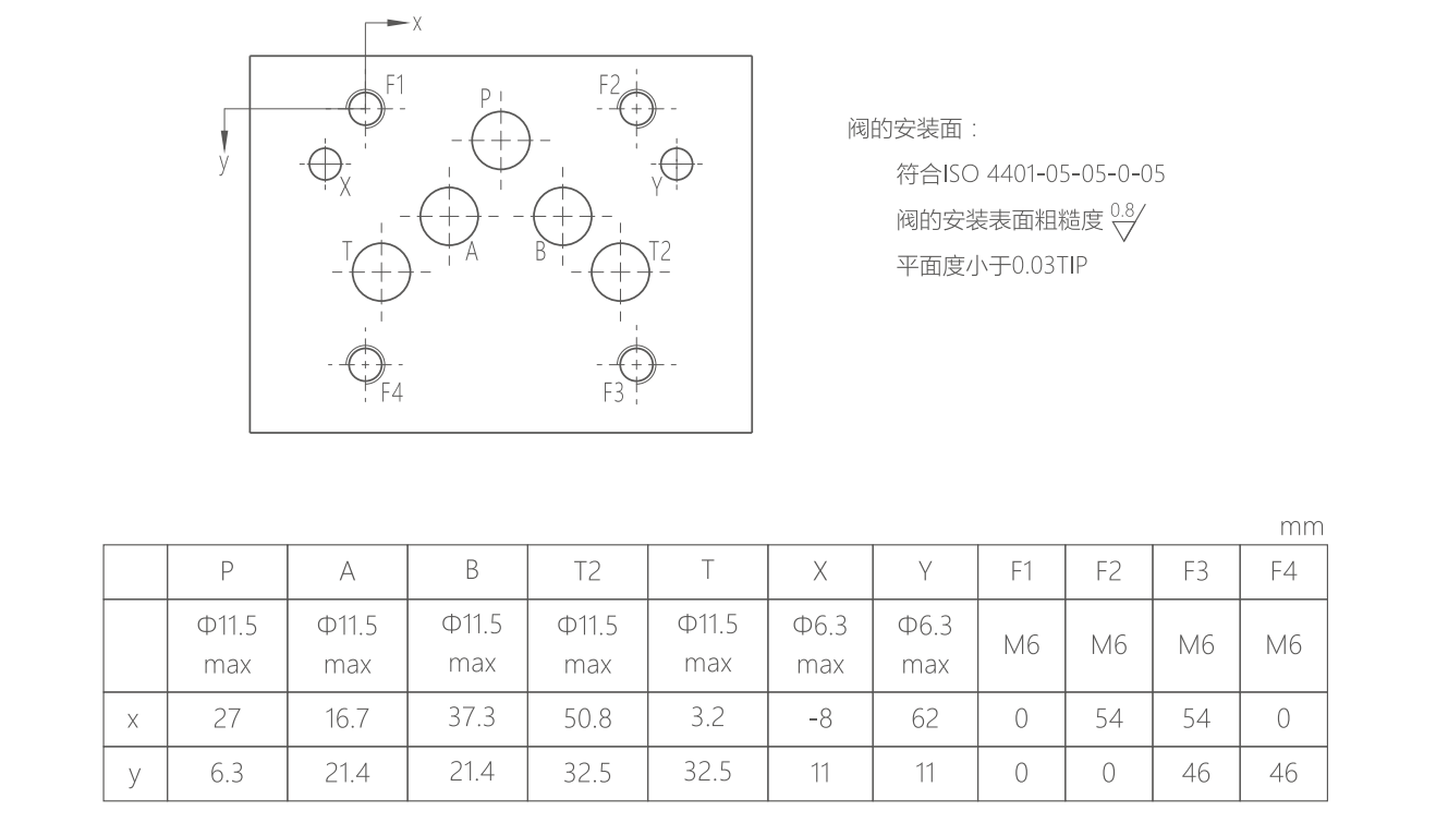
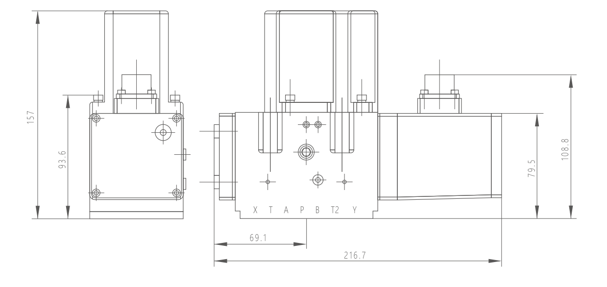
FF-661 Outline Drawing and Installation Dimensions
Verify manifold port layout, mounting bolt clearance, and overall envelope dimensions prior to replacing an existing Moog D661 servo valve. Fluid cleanliness directly governs metering-edge wear, null stability, resolution, pressure gain, and internal leakage; maintaining NAS Class 5 to Class 7 filtration ensures long-term servo accuracy.
For model selection assistance, Moog D661 cross-reference verification, or factory-direct pricing, review the proportional and servo valve catalog or submit technical requirements via the Huafilter engineering contact page.