Understanding a hydraulic flow control valve diagram is essential for reading hydraulic schematics, diagnosing actuator speed issues, and sizing replacement components.
A hydraulic flow control valve diagram uses ISO 1219-1 graphic symbols to represent how a valve restricts fluid flow, compensates for pressure variations, and regulates actuator speed in industrial hydraulic systems.
What is the ISO 1219-1 Symbol for a Hydraulic Flow Control Valve?
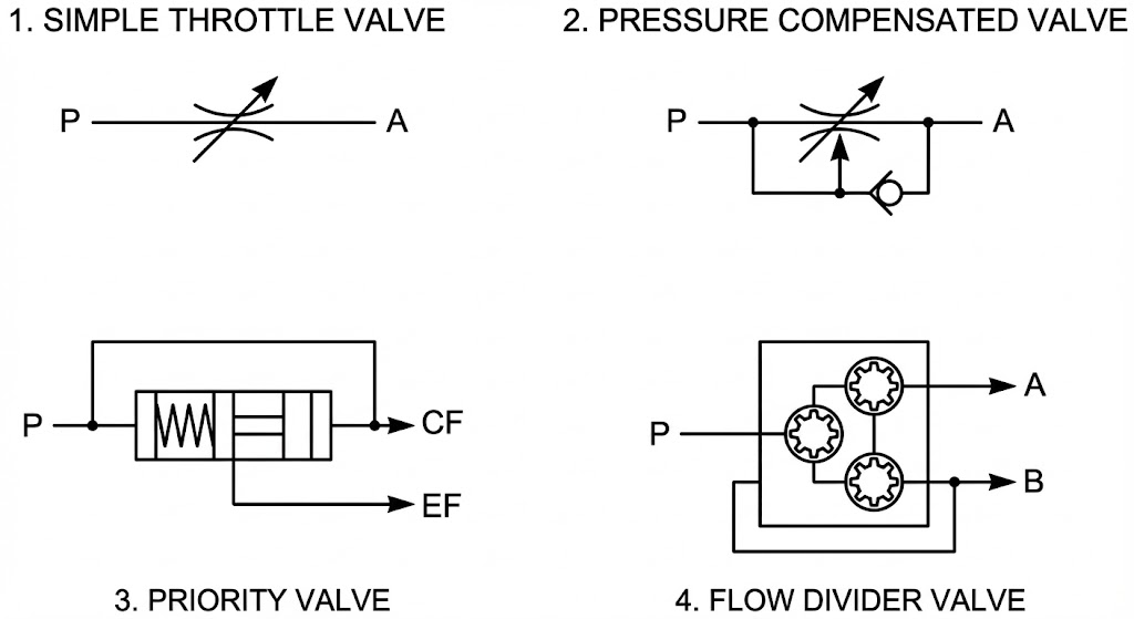
The standard ISO 1219-1 symbol for a basic hydraulic flow control valve consists of two opposing arcs representing a throttling orifice, combined with a diagonal arrow indicating manual adjustability.
- Fixed Orifice: Represented by two stationary curved lines
) (, indicating a non-adjustable flow restriction. - Adjustable Throttle (e.g., Huade DV/DRV Series): Adds a diagonal arrow (↗) across the throttling arcs, showing manual knob or screw adjustment.
- Single-Direction Throttle Check Valve (e.g., Huade Z2FS Series): Combines an adjustable throttle symbol in parallel with a spring-loaded ball check valve.
How Does a Pressure-Compensated Flow Control Valve Symbol Work?
A pressure-compensated flow control valve symbol adds a vertical pressure-sensing arrow and a compensator spool rectangle in series with the manual throttle.
A pressure-compensated flow control valve (such as the Huade 2FRM series) maintains a constant fluid flow rate regardless of system load variations by automatically adjusting an internal pressure compensator spool to keep a fixed pressure drop (ΔP = 0.5 to 1.0 MPa) across the throttling orifice.
Key Functional Components:
- Manual Throttle Orifice: Sets the target flow rate (Q = Cd · A · √(2ΔP / ρ)).
- Pressure Compensator Spool: Automatically adjusts its opening based on load pressure feedback.
- Rexroth/Huade 2FRM Equivalent Design: Ensures constant cylinder extension speed whether the load is 50 bar or 250 bar.
For complete technical specifications and CAD drawings of load-independent valves, consult our Huade 2FRM Pressure Compensated Flow Control Valve Catalog.
What is the Difference Between Meter-In, Meter-Out, and Bleed-Off Circuits?
On a hydraulic schematic, the position of the flow control valve relative to the actuator determines whether the circuit operates as a meter-in, meter-out, or bleed-off configuration.
1. Meter-In Circuit Dynamics
In a meter-in circuit, the flow control valve restricts fluid entering the cylinder cap end. The pump operates at the relief valve pressure setting (Prelief), and excess fluid bypasses over the main relief valve.
Formula for Inlet Pressure: P1 = Fload / Acap
Application Note: Do not use meter-in throttling on lowering booms or winch drives where gravity can pull the load faster than the inlet flow.
2. Meter-Out Circuit Dynamics
In a meter-out circuit, the flow control valve (such as a Huade Z2FS sandwich throttle valve) restricts fluid escaping from the cylinder rod end, creating hydraulic back pressure.
Pressure Intensification Formula: Prod = (Ppump · Acap + Fload) / Arod
Safety Warning: Due to cylinder area ratios (e.g., 2:1), rod-side pressure (Prod) can double the pump supply pressure. Ensure all fittings and subplates are rated for intensified pressure.
How to Diagnose Flow Control Valve Failures Using Schematics
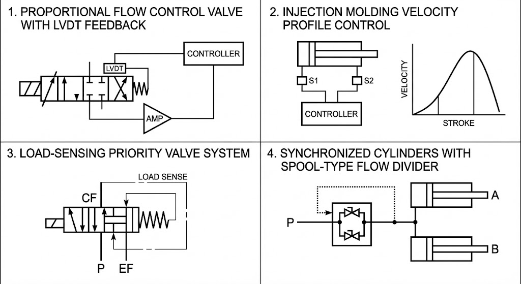
When a hydraulic actuator exhibits speed instability or unresponsiveness, technicians can isolate the faulty component by comparing schematic symbols against test gauge readings.
1. Actuator Speed Drops as Hydraulic Oil Heats Up
- Diagram Indicator: The schematic shows a basic throttle symbol without a temperature compensation mark (thermometer icon).
- Root Cause: Oil viscosity drops as fluid temperature rises from 30°C to 60°C. In laminar flow passages, lower viscosity increases flow leakage.
- Solution: Replace standard needle valves with sharp-edged orifice valves (such as the Huade 2FRM 6 series), where turbulent flow minimizes viscosity sensitivity.
2. Cylinder Drifts in Neutral Position
- Diagram Indicator: The schematic depicts a meter-out configuration with a closed-center directional control valve.
- Root Cause: High trapped pressure on the cylinder rod side causes micro-leakage across worn spool clearances inside the flow control valve.
- Solution: Install a pilot-operated check valve or zero-leak poppet valve directly on the cylinder port.