In industrial hydraulic schematics, a proportional directional valve symbol (ISO 1219-1 standard) represents an electro-hydraulic control valve engineered to provide continuous, non-binary flow rate and directional fluid control. Understanding these standardized symbols is essential for reading hydraulic circuit diagrams, troubleshooting system instability, and selecting direct drop-in replacements for Bosch Rexroth and Huade proportional valves, including the 4WRE and 4WRZ series.
Misreading an ISO 1219-1 schematic symbol often leads to improper electrical driver wiring, incorrect pilot drain plumbing, or selecting non-equivalent replacement valves. This guide breaks down the graphical logic of proportional hydraulic valve symbols into clear, actionable engineering facts.
What Makes a Valve Symbol “Proportional”? (The ISO 1219-1 Anatomy)
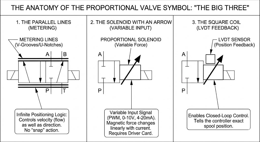
A proportional valve symbol is identified in ISO 1219-1 hydraulic schematics by three core graphical features: parallel metering lines enclosing the spool boxes, a diagonal arrow intersecting the solenoid coil, and a square box representing an LVDT position sensor.
- Parallel Lines: Indicate continuous throttling and infinite spool positioning capability across the stroke.
- Solenoid with Arrow: Indicates a variable analog or PWM electrical input signal.
- LVDT Square Box: Indicates closed-loop spool position feedback.
1. Parallel Lines: The Metering Logic
The most critical visual feature of a Proportional Directional Control Valve (PDCV) symbol is the pair of horizontal lines drawn parallel to the top and bottom of the valve spool rectangles.
Standard switching directional valves (such as binary 4/3 solenoid valves) do not have these parallel lines. In standard valves, the spool snaps completely open or completely closed.
In a proportional valve symbol, these parallel lines signify precision-machined V-grooves or U-notches on the valve spool land. These grooves allow the valve to throttle hydraulic fluid continuously. The spool can hover at 10%, 50%, or 90% stroke, controlling fluid velocity (flow rate) in direct proportion to the electrical command signal.
2. Proportional Solenoid with Arrow: Electrical Input
A standard solenoid symbol consists of a simple rectangle containing a single diagonal slash. This graphical notation represents a binary (On/Off) solenoid coil.
A proportional solenoid symbol adds a small arrow pointing through the diagonal slash. This arrow indicates that the magnetic force generated by the coil changes proportionally with the input electrical current.
- Signal Requirements: Proportional solenoids require an electronic driver card providing Pulse Width Modulation (PWM) or analog control signals (typically 0–10V or 4–20mA).
- Wiring Warning: Connecting a proportional solenoid directly to a standard 24V DC relay switch will cause the valve to actuate violently as a binary valve, eliminating all metering control.
3. LVDT Feedback Box: Closed-Loop Control
High-precision proportional valves feature a small square box attached to the solenoid symbol. This box represents a Linear Variable Differential Transformer (LVDT).
The LVDT continuously measures the physical position of the valve spool and feeds this data back to the On-Board Electronics (OBE) or external amplifier.
- Open-Loop Proportional Valve (No LVDT): Spool position depends on spring force and hydraulic flow forces. (e.g., Huade 4WRA / Rexroth 4WRA series).
- Closed-Loop Proportional Valve (With LVDT): The electronic driver actively adjusts solenoid current to maintain exact spool position despite fluid flow forces. (e.g., Huade 4WRE / Rexroth 4WRE series).
ISO 1219 Comparison: Switching vs. Proportional Valves
Use this quick technical reference table to compare standard directional valves with proportional models:
Decoding Advanced Features: OBE and Fail-Safe Positions
Modern industrial proportional valves integrate control electronics directly onto the valve body.
On-Board Electronics (OBE)
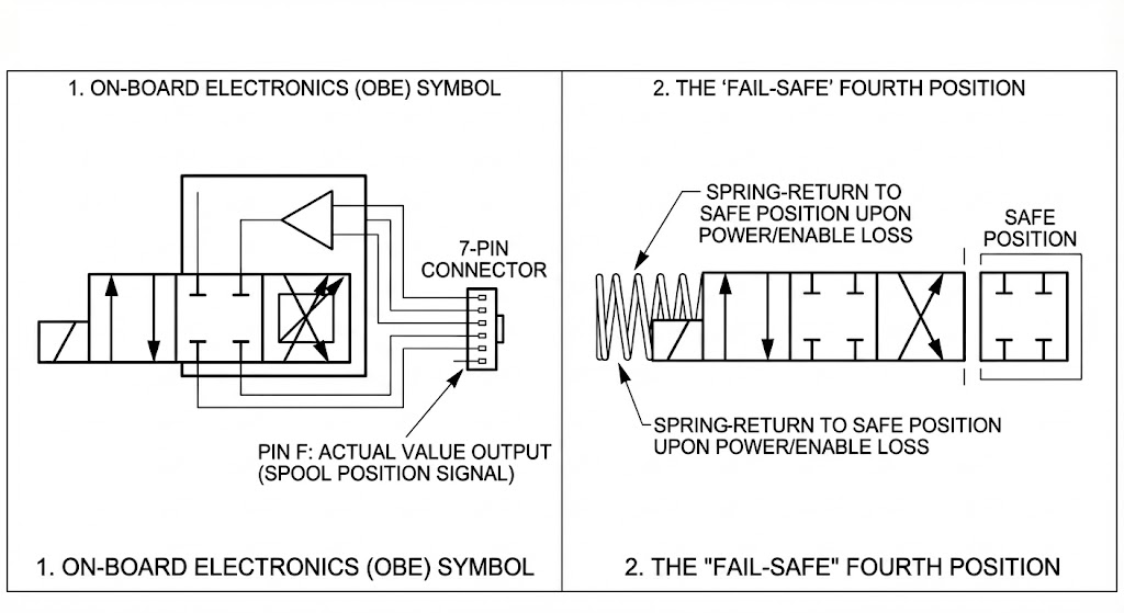
An OBE valve is represented in schematics by a solid rectangular enclosure surrounding both the solenoid and an amplifier triangle symbol.
- Wiring Specification: OBE valves do not require an external driver card in the electrical cabinet. They connect directly to the PLC via a standardized 7-pin connector (e.g., Main Supply, Command Signal, Signal Common, and Pin F Output).
- Troubleshooting Tip: Pin F provides the "Actual Value Output" (spool position feedback signal), allowing technicians to verify spool displacement using a standard multimeter during diagnostics.
The Fail-Safe 4th Position
High-flow proportional directional valves (such as the Huade 4WRZ / Rexroth 4WRZ series) often feature a 4th box separated to one side of the standard 3-position symbol.
Safety Function: This represents the Fail-Safe position. If electrical power or the "Enable" signal is lost, a heavy mechanical spring forces the spool into this 4th box (typically blocking all ports) to prevent uncontrolled machine movement.
3 Common Schematic Reading Mistakes in Hydraulic Systems
Glossing over minor graphical details in ISO schematics often results in severe operational errors and component damage:
- Ignoring the "Y" External Drain Port: Pilot-operated proportional valves often feature a dashed pilot line labeled "Y" leading to the reservoir tank. If this Y-port is plugged or combined with a pressurized return line, backpressure will destabilize the pilot stage, causing severe valve oscillation.
- Confusing Proportional Valves with Servo Valves: While both control flow continuously, ISO 1219 uses a distinct Torque Motor symbol for true servo valves. Proportional directional control valves (such as the Huade 4WRE series) feature positive spool overlap (creating a deadband), whereas servo valves feature zero spool overlap (axis cut). Replacing a servo valve with a proportional valve creates a control "dead zone" and sluggish loop response.
- Assuming Blocked Center Means Zero Leakage: A blocked center symbol in a proportional valve does not guarantee zero fluid flow. Because proportional spools rely on a precision clearance fit within the valve housing, internal spool leakage (quiescent flow) always exists. Load-holding applications require separate pilot-operated check valves.
Sourcing Drop-in Equivalent Proportional Valves
When replacing worn proportional valves or designing new hydraulic manifolds, selecting ISO-compliant components ensures seamless mechanical and electrical compatibility.
For complete technical specifications, CAD models, and model cross-reference tables, explore our full catalog of Huade proportional directional valves (4WRE and 4WRZ series), which serve as direct drop-in replacements for standard Bosch Rexroth industrial valves.
If you require assistance interpreting an ISO 1219-1 schematic or matching a Rexroth part number, contact our engineering support team today.