In control valve sizing, FL (Liquid Pressure Recovery Factor) is a dimensionless coefficient that measures a valve's ability to recover static pressure after the vena contracta in liquid service. xT (Terminal Pressure Drop Ratio Factor) is the dimensionless ratio that defines the critical pressure drop limit at which compressible gas or vapor flow chokes and reaches sonic velocity.
Together, FL and xT dictate the aerodynamic and hydrodynamic flow limits defined in IEC 60534-2-1 and ANSI/ISA-75.01.01 standards. Understanding these two coefficients prevents valve cavitation, eliminates choked flow miscalculations, and ensures accurate flow capacity sizing.
1. What is FL (Liquid Pressure Recovery Factor)?
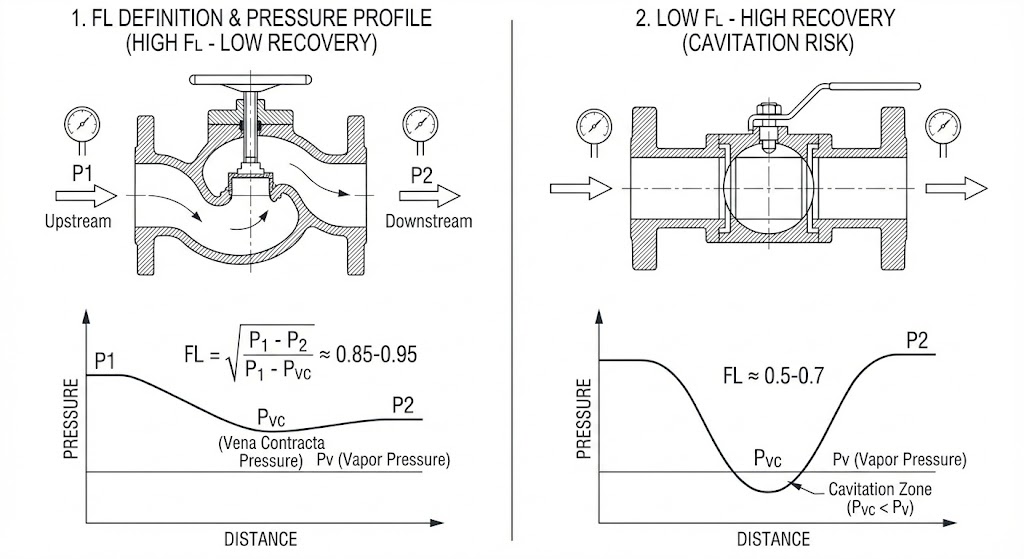
The Liquid Pressure Recovery Factor (FL) quantifies the efficiency of static pressure recovery between the vena contracta (minimum internal pressure point) and the valve outlet.
Where:
- P1: Upstream absolute pressure (bar or psi).
- P2: Downstream absolute pressure (bar or psi).
- Pvc: Absolute pressure at the internal vena contracta.
How to Interpret the FL Value:
- High FL Values (0.85 – 0.98) — Low Pressure Recovery: The valve dissipates kinetic energy through tortuous flow paths. The vena contracta pressure remains relatively close to downstream pressure P2. Typical of globe-style control valves.
- Low FL Values (0.20 – 0.70) — High Pressure Recovery: The fluid accelerates through an unobstructed orifice and rapidly recovers static pressure downstream. Typical of ball and butterfly valves.
2. How Does FL Predict and Prevent Valve Cavitation?
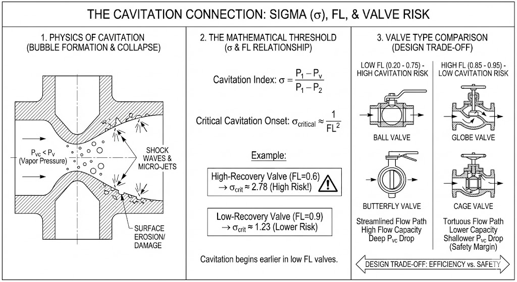
Cavitation in liquid control valves occurs when fluid pressure drops below liquid vapor pressure (Pv) at the vena contracta, followed by violent bubble collapse as pressure recovers downstream.
The cavitation index σ (Sigma) defines the fluid operating margin:
The Mathematical Link Between FL and Cavitation:
Choked cavitation flow begins when the cavitation index reaches the critical threshold:
- Low-Recovery Globe Valves (FL = 0.90): Choking begins only when actual pressure drop reaches 81% of effective inlet pressure (P1 − Pv). These valves offer superior cavitation resistance.
- High-Recovery Ball Valves (FL = 0.60): Choking initiates when pressure drop reaches just 36% of effective inlet pressure. High recovery drastically accelerates cavitation onset.
FL Values by Valve Trim Architecture
3. What is xT (Pressure Drop Ratio Factor) in Gas Sizing?
The Pressure Drop Ratio Factor (xT) defines the normalized pressure drop (ΔP / P1) at which a control valve reaches maximum mass flow capacity under compressible gas or steam flow.
When the operational pressure drop ratio x = (P1 − P2) / P1 exceeds the product of Fk · xT, gas velocity reaches local sonic speed (Mach 1) at the vena contracta. Further reductions in downstream pressure P2 produce zero increase in mass flow rate.
Impact of Specific Heat Ratio (Fk):
Standard xT testing uses air with a specific heat ratio k = 1.40. For other industrial gases, the factor Fk modifies the choking limit:
- Argon & Helium (Monatomic, k = 1.67): Fk ≈ 1.19. Resists choking at higher pressure drops.
- Propane & Butane (Polyatomic, k = 1.13): Fk ≈ 0.81. Chokes at significantly lower pressure drops.
4. How Valve Geometry Shapes xT and Aerodynamic Noise
Internal trim geometry determines both the choking threshold (xT) and the acoustic noise radiated by supersonic shock waves:
According to IEC 60534-8-3 acoustic calculation models, valves with low xT values generate downstream shock cells when x > xT. These shock waves convert aerodynamic energy directly into intense structural pipe vibration and acoustic radiation.
5. Piping Geometry Corrections: Understanding FLP and xTP
Factory datasheets publish FL and xT values measured under ideal straight-pipe conditions. When control valves are installed between pipe reducers or expanders, piping geometry factors alter the effective recovery coefficients to FLP and xTP.
Where:
- ΣK: Sum of velocity head loss coefficients for upstream and downstream reducers.
- Cv / d2: Relative valve capacity per unit internal port area squared.
Engineering Consequence:
Pipe reducers pre-accelerate inlet fluid before the trim. This area restriction reduces the installed recovery factor (FLP < FL), causing liquid cavitation and gas choking to occur at lower system pressure drops than manufacturer catalog curves suggest.
6. Industrial Application: Flow Control Valves in High-Pressure Hydraulics
While process pipelines utilize pneumatic globe valves, industrial hydraulic systems operating at 210 to 350 bar require high-integrity fluid throttle architecture. At extreme hydraulic pressure drops, fluid velocity across metering orifices frequently triggers localized cavitation and severe valve spool erosion.
To stabilize volumetric flow and prevent cavitation erosion, industrial hydraulic manifolds incorporate specialized Huade hydraulic flow control valves. These industrial valves utilize pressure-compensated orifices and multi-stage metering profiles:
- Modular Throttle Check Valves (Huade Z2FS Series): Sandwich plate design providing dual-direction flow restriction with high FL stability across full spool stroke.
- 2-Way Pressure-Compensated Flow Control Valves (Huade 2FRM Series): Maintains stable actuator speed independent of fluctuating circuit load pressures.
Sizing Checklist for Engineers:
- Verify Throttling Travel: Never use full-open FL values for throttling sizing; evaluate FL at normal operational stroke (30% to 70%).
- Distinguish Flashing vs. Cavitation: High FL trims eliminate cavitation but cannot prevent flashing when downstream pressure P2 ≤ Pv.
- Check Gas Choking Threshold: Ensure operational pressure ratio x < Fk · xT to maintain predictable linear mass flow control.