Axial piston pump overheating occurs when operating hydraulic fluid temperature exceeds the continuous thermal threshold of 82°C (180°F), primarily driven by excessive internal volumetric bypass leakage (slippage), fluid aeration, cavitation, or misaligned pressure compensator settings.
Sustained high-temperature operation accelerates hydraulic oil viscosity breakdown, degrades elastomer nitrile (NBR) or fluorocarbon (FKM) shaft seals, and induces thermal galling across precision micro-clearance interfaces in industrial variable displacement pumps such as Bosch Rexroth A10VSO, A4VSO, and A7V series.
Operating Temperature Thresholds for Axial Piston Pumps
Hydraulic fluid power systems require precise operating temperature ranges to preserve fluid film lubrication between the rotating cylinder barrel and the port valve plate. Temperature diagnostics must be conducted using calibrated infrared thermography or in-line immersion thermal sensors.
Operating an axial piston pump above 90°C causes thermal degradation of zinc-dialkyldithiophosphate (ZDDP) anti-wear additives, resulting in boundary lubrication breakdown and accelerated adhesive wear on bronze piston slipper assemblies.
Internal Volumetric Leakage and Heat Generation
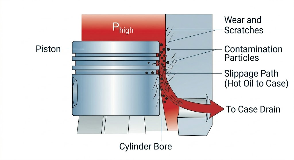
Internal volumetric bypass leakage—commonly termed slippage—is the primary mechanical source of localized thermal energy in positive displacement pumps.
Hydraulic pistons, cylinder block bores, and port plate running faces are separated by hydrodynamic lubricating micro-gaps measuring 3 to 8 microns. When solid particulate contamination erodes these running surfaces, high-pressure fluid bypasses the displacement chambers directly into the pump outer casing.
Thermodynamic Power Loss Equation:
The energy converted directly into fluid heat through internal pressure drop is calculated using the following thermodynamic formula:
Where:
- Ploss = Thermal power dissipation into hydraulic fluid (kW)
- Δp = Working pressure differential from system line to case drain (bar)
- Qleak = Volumetric flow rate of case drain bypass leakage (L/min)
The Case Drain Permissible Flow Standard:
In healthy axial piston pumps, continuous case drain leakage should measure between 3% and 5% of total rated displacement flow. When case drain flow exceeds 8% to 10%, pressure energy drops across internal clearances without performing external mechanical work, generating continuous heat that degrades shaft seals and warps cylinder block faces.
Cavitation and Aeration in Hydraulic Suction Lines
Fluid dynamic instability in pump inlet conduits generates localized high-temperature spikes through rapid vapor bubble formation and collapse.
1. Vaporous Cavitation
Cavitation occurs when inlet fluid pressure drops below the saturation vapor pressure of the hydraulic oil, typically induced by restricted suction strainers, undersized inlet piping, or cold-fluid high viscosity. When vapor cavities enter the high-pressure discharge zone, the bubbles collapse violently. Micro-implosions generate localized micro-jets with impact pressures exceeding 1,500 bar and instantaneous thermal spikes surpassing 1,000°C (1,832°F), eroding bronze port bridges.
2. Aeration and Micro-Dieseling
Aeration is the entrainment of free air bubbles into the hydraulic stream through loose suction flange fittings, deteriorated shaft seals, or low reservoir oil levels. As entrained air bubbles pass into the compression zone of the cylinder barrel, rapid adiabatic compression ignites the surrounding oil-air boundary mixture. This combustion mechanism, termed micro-dieseling, turns hydraulic fluid dark through thermal oxidation and elevates bulk reservoir temperatures.
Pressure Compensator and System Relief Valve Coordination
A fundamental hydraulic circuit design error that induces extreme thermal loading is improper pressure differential coordination between the variable pump pressure compensator and the downstream system relief valve.
[ Faulty Setting ] : Relief Valve < Pump Compensator ──► Continuous High-Pressure Dump to Tank (100% Heat Generation)
In a variable displacement load-sensing or pressure-compensated circuit (such as A10VSO with DR or DFR1 controls), the pump automatically destrokes to near-zero flow once target system pressure is achieved.
If a technician sets the system relief valve lower than or equal to the pump compensator setpoint:
- System pressure reaches the relief valve threshold first.
- The relief valve opens, dumping fluid directly to the reservoir tank.
- The pump never reaches its internal compensator setpoint and remains at full swashplate displacement.
- The entire electrical input motor power is converted directly into heat across the relief valve orifice.
Engineering Requirement: Always calibrate the primary system relief valve at least 17 to 20 bar (250 to 300 PSI) above the maximum setpoint of the axial piston pump compensator.
Preventative Maintenance Protocols for Overheating Pumps
To prevent thermal degradation and catastrophic component seizure, maintenance engineers must implement standardized diagnostic procedures:
- Monitor Case Drain Flow Rates: Install permanent in-line flow meters or conduct periodic container tests on the pump case drain line. Increasing baseline leakage indicates progressive wear on the valve plate or piston slipper retention plates.
- Conduct Spectrometric Fluid Analysis: Monitor oil samples for elevated Copper (Cu) and Bronze levels. Particulate concentrations exceeding baseline thresholds indicate abrasive wear on the valve plate running surface.
- Inspect Heat Exchanger Thermal Gradient: Measure differential fluid temperatures across the hydraulic oil cooler. Cooler fin clogging or low coolant flow severely limits dissipation capacity, causing baseline thermal escalation.
- Verify Reservoir Breather Integrity: Ensure hydraulic reservoir desiccant breathers prevent negative pressure formation in sealed tanks, avoiding vacuum-induced suction line cavitation.
Replacement Axial Piston Pumps and Technical Sourcing
When internal surface scoring causes unrecoverable volumetric efficiency loss and continuous thermal escalation, replacing worn rotating groups or complete pumps is necessary to prevent machine downtime.
Precision-manufactured aftermarket units engineered to ISO 3019 mounting flange standards provide 100% mechanical and hydraulic interchangeability with original European models.
For engineering dimensions, displacement performance curves, and direct cross-reference charts for Bosch Rexroth A10VSO, A4VSO, and A2FO series, explore our Industrial Axial Piston Pumps Catalog.
For technical verification of existing type codes or assistance resolving chronic hydraulic overheating, Contact Huafilter Technical Support for component cross-referencing and engineering support.