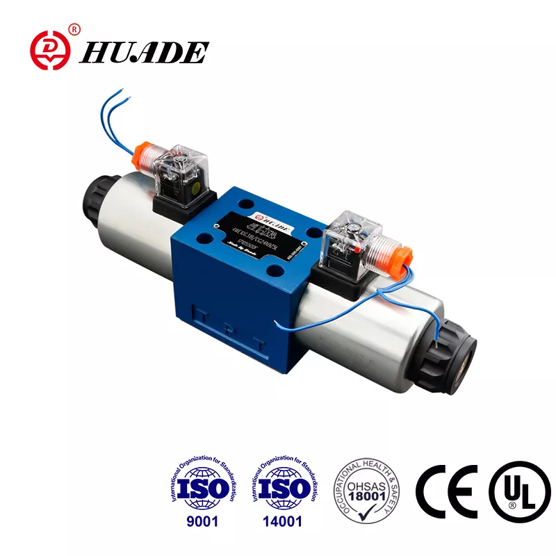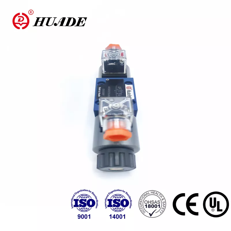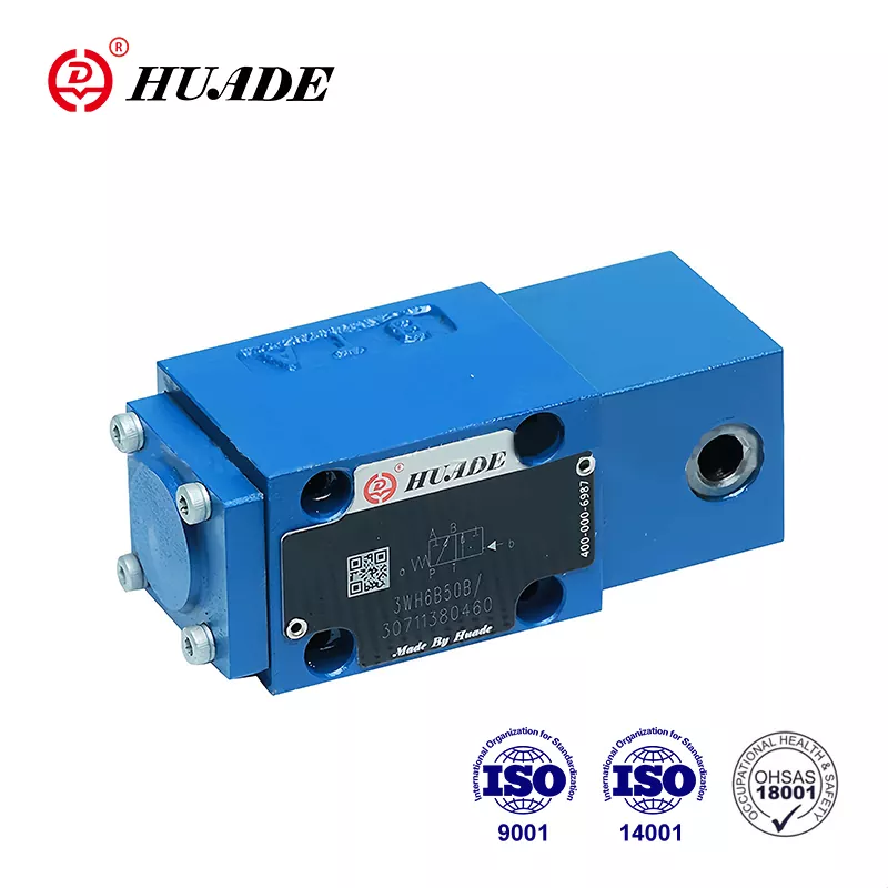
Directional Control Valve Rexroth Interchangeable

Directional Control Valve WH

MANUFACTURER Genuine Huade Hydraulic
STANDARDS ISO 4401 / DIN 24340
AVAILABILITY Factory Direct Stock
TECHNICAL REPLACEMENT NOTICE

This Huade® directional control valve serves as a 100% direct drop-in replacement for Bosch Rexroth DIRECTIONAL-CONTROL-VALVE-WH equivalents. Dimensions, mounting interfaces, and technical parameters are identical. Designed for cost reduction in industrial and mobile hydraulic systems.

• Product features: Direct operated spool valve, hydraulically/pneumatically operated, Rexroth-compatible design with detent options
• Specifications: Size 6/10, max pressure 31.5MPa, flow up to 60/120 L/min, subplate mounting ISO4401/CETOP-RP121H
• Applications: Marine hydraulic systems, industrial flow control for stop/start/direction operations

Request B2B Quote

Submit your target quantity and technical questions. Our hydraulic engineering team will provide a factory-direct quote and lead time estimate within 24 hours.

Send Product Inquiry 📥 Download PDF Datasheet
100% Genuine Huade Direct factory authorized supply
ISO 4401 Mounting ISO 4401 / Rexroth interchangeable
Secure Packaging Sealed rust-proof global shipping

Technical Data Sheet

  • Product Overview
  • Features & Applications
  • Technical Parameters

Product Overview

As a leading manufacturer in China's hydraulic industry, Huade Hydraulic has had two long-term cooperation experiences with Rexroth. Huade® directional control valve type WH is more advanced in technology and more durable than the similar products in this line. Huade operates more than 750 pieces advanced production equipment imported from all over the world to ensure the high quality of hydraulic products. It is more advanced in technology and more durable than the similar products in this line. The factory comes up to the international standards,namely, ISO9001, ISO14001 and OH SAS18001. The series of directional valves produced by Huade Hydraulic are widely used in marine hydraulic system. Huade owns a huge customer group in the marine industry.

With symbols A and B port T must be used as a leakage port if the operating pressure is greater than 16.0 MPa

Symbol Q6%of nominal cross-sectional area

Symbol W, 3% of nominal cross-sectional area

Pressure fluid temperature range (℃)

Viscosity range                              (mm2/s)
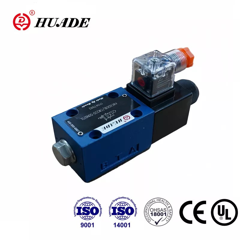
Key Features

  • Direct operated directional spool valve
  • Two position valve with stroke limit optional
  • Subplate mounting
  • Mounting pattern to Din 24 340 form A, ISO 4401 and CETOP - RP 121H

Industrial Applications

  • WH valves are hydraulic operated directional spool valves.They are used for the control of stop, start and direction of a flow
  • The directional valves mainly consist of housing (1), one or two operating elements (2) (hydraulically, pneumatically operating cylinder), the control spool (3), as well as one or two return springs (4).
  • At rest the control spool (3) is kept in the centre or starting position by the return springs (3) (except impulse valve).
  • The control spool (3) is pushed into the required switching position by the operating elements.
  • With detent, type ..OF/.
  • Hydraulically or pneumatically operated directional valves are also available as 2-position valves with detent (5). When the operating elements with detent are used every switching position may be locked.
  • Without return spring, without detent, type..O/.
  • When using operating elements without return spring and without detent, there is no defined switching position at rest.
  • Structure diagram
  • Cartridge throttle
  • The use of a cartridge throttle is then necessary when during the switching procedures in the given operating conditions flows occur which exceed the performance limits of the valve.
  • It is plugged into the P-channel of the directional valve.

Technical Parameters

Mechanical ratings and operating limits for the Directional Control Valve WH:

Parameter / Dimension Name Value / Rating Specification
Size - 6 10
Max.operating pressure - Ports A, B,P(MPa) - to 31.5 to 31.5
Max.operating pressure - Port T (MPa) - to 16 to 16
With symbols A and B port T must be used as a leakage port if the operating pressure is greater than 16.0 MPa With symbols A and B port T must be used as a leakage port if the operating pressure is greater than 16.0 MPa
Flow max (L/min) - up to 60 up to 120
Operating to flow (Spool position 0) - Symbol Q6%of nominal cross-sectional area Symbol Q6%of nominal cross-sectional area
Operating to flow (Spool position 0) - Symbol W, 3% of nominal cross-sectional area Symbol W, 3% of nominal cross-sectional area
Fluid - Mineral oil or phosphate ester Mineral oil or phosphate ester
Pressure fluid temperature range (℃) - -20~+80 -20~+80
Viscosity range                              (mm2/s) - 2.8~500 2.8~500
Weight(kg) - 1 operating cylinder - approx.2 approx.3.5
Weight(kg) - 2 operating cylinder - approx.2.2 approx.4.5
Plot pressure(MPa) - min - 0.6 to 1> tank pressure 0.5
Plot pressure(MPa) - max - 20 6