For complete selection guidelines and cross-reference documentation on this product line, please consult our proportional flow control valve alternatives.
Ever watched your hydraulic equipment suddenly slow to a crawl? Or noticed your water system pressure acting weird? Nine times out of ten, the culprit is a flow control valve that needs some attention. If you’ve been scratching your head wondering how to fine-tune these crucial components, you’re in the right place.
Flow control valves are like the volume knobs of fluid systems – they control how fast liquid or gas flows through pipes. Just like adjusting your car’s cruise control, getting these valves dialed in properly can mean the difference between smooth operation and costly breakdowns.
Whether you’re troubleshooting valve adjustment issues in hydraulic systems, managing water flow in industrial processes, or fine-tuning pneumatic equipment, this complete guide will walk you through everything you need to know about adjusting flow control valves safely and effectively.
What Is a Flow Control Valve?

A flow control valve is a device that controls how much fluid (liquid or gas) passes through a pipe or system. Think of it like a faucet in your kitchen – you can turn it to let more or less water flow out. But flow control valves are much more precise and are used in industrial systems, machinery, and equipment.
According to the International Society of Automation (ISA), flow control valves are fundamental components in industrial process control, serving as the final control elements that regulate fluid flow rates to maintain desired system performance.[1]
Why Flow Control Valves Matter
These valves are crucial because they:
- Control the speed of hydraulic cylinders and motors
- Prevent system damage from too much pressure
- Save energy by optimizing flow rates
- Ensure smooth operation of machinery
- Help maintain consistent performance
When a flow control valve isn’t adjusted properly, you might notice:
- Equipment running too fast or too slow
- Jerky or rough movements in hydraulic systems
- Wasted energy and higher costs
- Premature wear on system components
Types of Flow Control Valves

Before we dive into adjustments, let’s look at the main types you’ll encounter:
Needle Valves
These use a pointed needle to control flow through a small opening. They’re great for precise control but create more pressure drop.
Best for: Fine-tuning flow in small systems, fuel mixtures, or delicate applications.
Globe Valves
These have a disc that moves up and down to control flow. They’re excellent for throttling (gradual flow control) but can be bulky.
Best for: Water systems, steam applications, and situations where you need good shut-off capability.
Butterfly Valves
These use a rotating disc to control flow. They’re quick to operate but less precise for fine adjustments.
Best for: Large pipe systems, quick shut-off applications, and systems where space is limited.
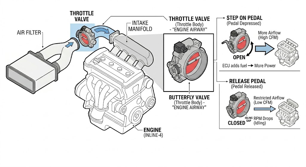
Throttle Valves
Simple valves that restrict flow through an adjustable opening. Common in pneumatic (air) systems.
Best for: Basic flow control in air systems and simple hydraulic circuits.
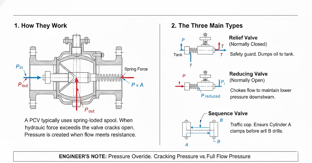
Pressure-Compensated vs. Non-Compensated Valves
This is an important distinction that affects how you’ll adjust your valve:
- How they work: Flow changes when system pressure changes
- Pros: Simple, reliable, and cost-effective
- Cons: Flow varies with pressure fluctuations
- Best for: Systems with stable pressure
- How they work: Maintain constant flow even when pressure changes
- Pros: Consistent performance regardless of pressure variations
- Cons: More complex and expensive
- Best for: Systems with varying loads or pressures
Research published in the journal Machines demonstrates that pressure-compensated flow control valves utilize internal compensator mechanisms to automatically adjust for pressure variations, thereby maintaining consistent flow rates under dynamic loading conditions.[2]
Industry Standards and Compliance
When adjusting flow control valves, it’s essential to follow established industry standards. The primary standards organizations governing valve design and testing include:[3][4]
-
ANSI/ISA Standards: The International Society of Automation publishes the ISA-75 series of standards, which provide comprehensive guidelines for control valve design, testing, and performance. Key standards include:
- ANSI/ISA-75.01.01 (Flow capacity sizing equations)
- ANSI/ISA-75.05.01 (Control valve terminology)
- ANSI/ISA-75.11.01 (Inherent flow characteristics and rangeability)
-
ISO Standards: The International Organization for Standardization provides globally recognized standards such as:
- ISO 5208 (Industrial valves pressure testing)
- ISO 6263 (Compensated flow-control valves mounting surfaces)
- ISO 6403 (Valves controlling flow and pressure test methods)
- API Standards: The American Petroleum Institute establishes standards particularly relevant to oil and gas applications, including API 598 for valve inspection and testing procedures.
These standards ensure safety, reliability, and interoperability across different valve manufacturers and applications.
Tools You’ll Need
Before starting any valve adjustment, gather these essential tools:
| Tool | Purpose |
|---|---|
| Flow meter | Measures actual fluid flow rate |
| Pressure gauge | Monitors system pressure |
| Adjustable wrench | Makes valve adjustments |
| Locknuts or clips | Secures your settings |
| Safety equipment | Protects you during work |
⚠️ Safety First: Important Precautions
Never skip safety steps! Working with pressurized systems can be dangerous. Here’s what you must do:
Before You Start:
- Turn off the system and release all pressure
- Wait for the system to cool down if it’s been running hot
- Wear safety glasses and gloves
- Have a coworker nearby in case of emergency
- Read the system manual for specific safety instructions
Lockout/Tagout Procedures:
- Lock and tag energy sources to prevent accidental startup
- Verify that all pressure is released
- Inform other workers about the maintenance work
Step-by-Step Guide to Adjusting Flow Control Valves

Step 1: Prepare for Adjustment
- Shut down the system safely following proper procedures
- Identify your target flow rate from system specifications
- Check the valve’s current position and note any existing settings
- Install your flow meter and pressure gauges if not already present
Step 2: Basic Adjustment Process
Start with small adjustments – never make big changes at once.
-
Turn the adjustment screw or knob slowly:
- Clockwise (tightening) = Less flow
- Counterclockwise (loosening) = More flow
- Make only 1/8 to 1/4 turns at a time
- Test the system after each small adjustment
Step 3: Monitor and Fine-Tune
- Fire up the system and watch that flow meter reading
- Compare what you’re seeing to what you want – are you hitting your target?
- Make tiny tweaks as needed – patience is key here
- Keep an eye on those pressure gauges to stay within safe limits
- Give the system a minute to settle after each adjustment – don’t rush it!
Recent research on digital hydraulic flow control demonstrates that proper adjustment timing is critical – systems require stabilization periods between adjustments to achieve accurate flow measurements.[5]
Step 4: Lock in Your Settings and Document Everything
Once you nail the perfect flow, it’s time to secure that adjustment.
- Use locknuts or clips to prevent the setting from drifting
- Test everything under normal working conditions – not just idle
- Write down your settings – trust me, you’ll thank yourself later
What to record:
- Initial valve position (turns from closed)
- Final flow rate achieved
- System pressure during operation
- Date of adjustment
- Any unusual observations
Adjusting Specific Valve Types
Needle Valve Adjustment
Needle valves require extra care because they’re very sensitive:
- Close the valve completely by turning clockwise until snug (don’t overtighten!)
- Open slowly by turning counterclockwise
- Make very small adjustments – 1/8 turns or less
- Watch the flow meter closely as changes happen quickly
Pro tip: If you’re adjusting a fuel mixture needle valve, start lean (less fuel) and gradually add more until you get smooth operation. This prevents flooding and potential damage.
Important note: After initial adjustment, you might need to fine-tune again once the system runs under full load for a while. Don’t be surprised if things drift slightly during the first few hours of operation.
Globe Valve Throttling
Globe valves are more forgiving for adjustments:
- Close the valve fully
- Open one full turn as a starting point
- Adjust gradually until you reach desired flow
These valves handle larger adjustments better than needle valves.
Pressure-Compensated Valve Adjustment
These valves are easier to adjust because they maintain consistent flow:
- Unlock the adjustment mechanism if it has a lock
-
Turn the adjustment knob.
Important: Check the valve label. Usually Clockwise = Less flow, but some manufacturers are opposite. - The internal compensator handles pressure variations automatically
- Lock the setting when you’re satisfied with the flow
As noted in hydraulic system research, pressure-compensated valves employ compensator spools that maintain constant flow by automatically adjusting for pressure changes, with damping mechanisms to prevent hunting between the pump and valve.[6]
Non-Compensated Valve Adjustment
These require more attention to system pressure:
- Monitor both flow and pressure during adjustments
- Use manufacturer’s charts to correlate settings with flow rates
- Be aware that pressure changes will affect your flow
- May need readjustment if system pressure varies during operation
Common Problems and Solutions
Possible causes: Dirt, corrosion, or lack of lubrication
Solution: Clean and lubricate the adjustment mechanism
Possible causes: Loose adjustment screw, worn components, system pressure changes
Solution: Double-check all locknuts are tight, replace worn parts if needed, consider upgrading to pressure-compensated valves for unstable systems
Possible causes: Cavitation, turbulent flow, valve undersized
Solution: Check if valve is properly sized for your application, reduce pressure drop, or install anti-cavitation trim
Possible causes: Worn seals, damaged valve body
Solution: Replace seals or entire valve if body is damaged
Possible causes: Clogged passages, worn internal parts
Solution: Clean valve internally, replace worn components
Understanding Cavitation in Control Valves

Cavitation is one of the most destructive phenomena affecting control valves. It occurs when the local pressure in the valve drops below the vapor pressure of the liquid, causing vapor bubbles to form. When these bubbles subsequently collapse in higher-pressure regions, they create shock waves that can cause severe damage to valve internals.[7]
According to research by Emerson, cavitation is characterized by four primary negative effects: high noise levels (often exceeding 110 dB), excessive vibration, material damage through pitting, and deterioration of flow control effectiveness.[8] The damage typically appears as a rough, cinder-like surface on valve components.
Prevention Strategies
Cavitation prevention is critical for valve longevity. Industry experts recommend several approaches:[9][10]
- Proper Valve Sizing: Ensure the valve is appropriately sized for the application to avoid excessive pressure drops
- Pressure Drop Staging: Use multiple valves in series or multi-stage trim designs to distribute pressure drop gradually
- Anti-Cavitation Trim: Install specialized trim with multiple flow paths that increase the cavitation coefficient (Xfz)
- System Design: Place valves at lower elevations or in cooler areas to increase downstream pressure
- Material Selection: Use hardened materials for valve components exposed to cavitation
The International Electrotechnical Commission standard IEC 60534-8-4 provides detailed methods for predicting cavitation and noise generation in control valves.[11]
Factors That Affect Valve Performance
Understanding these factors will help you make better adjustments:
-
Fluid Properties: Thick fluids (high viscosity) flow slower than thin fluids; temperature changes affect fluid thickness; corrosive fluids may require special valve materials.
Research indicates that valve parameters such as core diameter, spring stiffness, and damping hole diameter significantly impact flow dynamic performance.[12] - System Design: Pipe size and layout affect pressure drop; proper valve sizing is crucial for good control; support and alignment prevent mechanical stress.
- Operating Conditions: Pressure fluctuations affect non-compensated valves more; temperature extremes can damage valve components; contamination in the fluid can clog valve passages.
Maintenance Tips for Optimal Performance
Regular Maintenance Tasks:
- Clean the valve and surrounding area monthly
- Check for leaks during routine inspections
- Lubricate moving parts according to manufacturer recommendations
- Replace filters to keep fluid clean
- Calibrate flow settings annually or as specified
Signs Your Valve Needs Attention:
- Difficulty making adjustments
- Inconsistent flow rates
- Unusual noises during operation
- Visible leaks or corrosion
- Erratic system behavior
Real-World Application Scenarios
Manufacturing Equipment
The problem: Your CNC machine’s hydraulic feed rate is inconsistent, causing poor surface finish
The solution: Adjust the flow control valve to maintain steady cutting speeds, improving product quality and tool life
HVAC Systems
The problem: Some rooms are too hot while others are freezing
The solution: Balance water flow through heating/cooling circuits by adjusting zone control valves
Hydraulic Lifts and Presses
The problem: Jerky movement or slow operation affecting productivity
The solution: Fine-tune flow control to achieve smooth, consistent speeds that match your process requirements
While many valve adjustments can be done by operators, call a professional when: The valve is part of a critical safety system, you’re unsure about proper procedures, the system uses hazardous fluids, multiple valves need coordinated adjustments, or you encounter unexpected problems during adjustment.
Conclusion
Adjusting flow control valves properly is a skill that improves with practice. Start with small adjustments, prioritize safety, and don’t rush the process. Remember that every system is different, so what works for one application might need modification for another.
The key to success is understanding your specific valve type, following proper safety procedures and industry standards, and making gradual adjustments while monitoring system performance. With patience and attention to detail, you’ll be able to optimize your system’s performance and extend the life of your equipment.
Keep this guide handy for reference, and don’t hesitate to consult your system’s manual or contact a professional when you’re unsure about any procedure. Proper valve adjustment is an investment in your system’s reliability and efficiency.
Quick Reference Checklist
Before Starting:
- ☑ System shut down and depressurized
- ☑ Safety equipment on
- ☑ Tools gathered
- ☑ Target flow rate identified
During Adjustment:
- ☑ Small incremental changes only
- ☑ Monitor flow and pressure
- ☑ Allow system to stabilize
- ☑ Record settings
After Adjustment:
- ☑ Settings locked in place
- ☑ System tested under normal conditions
- ☑ Performance documented
- ☑ Maintenance scheduled
Remember: When in doubt, consult with an experienced technician or the valve manufacturer for guidance specific to your system. Always refer to applicable ANSI, ISA, and ISO standards for your specific valve type and application.
References
- International Society of Automation (ISA). ISA 75.05.01-2016: Control Valve Terminology.
- Investigation on the Dynamic Characteristics of a New High-Pressure Water Hydraulic Flow Control Valve. Machines, 2024.
- Valve Standards – American National Standards Institute (ANSI), International Organization for Standardization (ISO), and International Society of Automation (ISA).
- ISA-75 Series of Standards for Control Valves. International Society of Automation.
- Digital hydraulic valves: Advancements in research. Heliyon, 2024.
- Hydraulic Flow Control Valve with Relief – Instruction Manual. Delavan Fluid Power.
- Cavitation in Control Valves – Technical Overview. CLA-VAL, 2020.
- Cavitation in Control Valves. Emerson Automation Solutions.
- Control Valve Cavitation and Noise Prevention. Valin Corporation.
- How to Prevent Cavitation in Butterfly Control Valves. ISA Blog, Hans D. Baumann, Ph.D., PE, 2021.
- Baumann, H.D. & Monsen, J.F. “Stop Cavitation from Destroying Your Control Valve Trims.” Valve World Magazine, 2018. Reference to IEC Standard 60534-8-4.
- Structure improvement and parameter optimization of micro flow control valve. Scientific Reports, 2023.