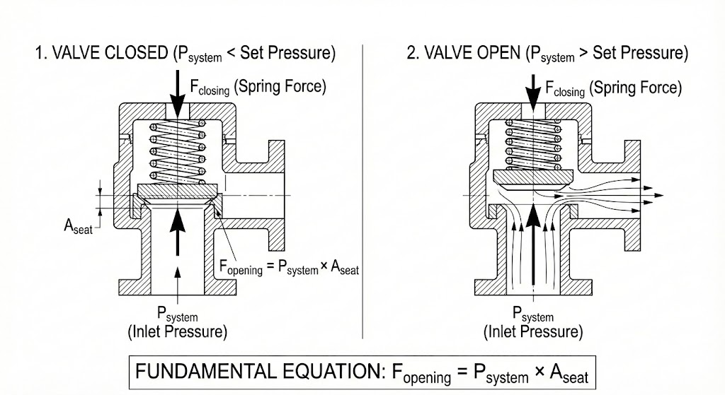
Direct pressure represents one of the most fundamental concepts in hydraulic engineering. At its core, the direct pressure principle follows the basic physics formula P = F/A, where pressure (P) equals force (F) divided by the surface area (A) over which that force acts. This mathematical relationship governs everything from simple hydraulic cylinders to complex control systems in industrial machinery.
For complete selection guidelines and cross-reference documentation on this product line, please consult our Rexroth pressure control valve equivalents.
In practical hydraulic applications, direct pressure refers to the immediate, unmodified pressure applied within a system. This differs from indirect or pilot-controlled pressure, where the main pressure is modulated through secondary control mechanisms. Understanding the distinction between direct pressure and modulated pressure matters because it directly affects how your hydraulic system responds under different operating conditions.
The efficiency of direct pressure systems stems from their straightforward force transmission. When hydraulic fluid pushes against a piston or valve element, the resulting direct pressure creates immediate mechanical action. This directness eliminates intermediate control stages, which explains why direct pressure components typically respond faster than their pilot-operated counterparts. Response times for direct pressure valves range from 2 to 10 milliseconds, compared to approximately 100 milliseconds for pilot-operated designs.
Safety Consideration
Efficiency comes with specific requirements for system control. Higher direct pressure applications demand more sophisticated safety mechanisms. A hydraulic system operating at 3000 PSI direct pressure requires far more robust pressure relief valves and monitoring equipment than a system running at 500 PSI. The relationship between applied force and system stability is not linear.
Direct Pressure Relief Valves vs Pilot-Operated Designs

The choice between direct pressure relief valves and pilot-operated relief valves represents a critical decision point in hydraulic system design. Both valve types protect against excessive pressure buildup, but they accomplish this goal through fundamentally different mechanisms that affect how direct pressure is managed within the system.
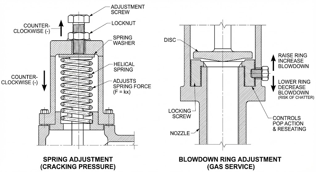
A direct pressure relief valve uses a spring-loaded poppet or ball that seats directly against the valve port. When system pressure exceeds the spring’s preset force, the valve element lifts, allowing fluid to bypass to the tank or reservoir. The valve’s cracking pressure—the point where it first begins to open—depends entirely on the spring’s physical characteristics and adjustment setting. This mechanical simplicity creates the fast response times that make direct pressure valves suitable for applications requiring immediate pressure protection.
Pilot-operated relief valves employ a two-stage design where a small pilot valve controls a larger main valve element. The pilot section senses system pressure and, when threshold levels are reached, redirects pressure to open the main valve. This indirect actuation allows pilot-operated valves to handle much higher flow rates while maintaining relatively stable pressure settings. However, the additional control stage introduces response delays that make them less suitable for applications requiring immediate direct pressure control.
| Parameter | Direct Pressure Valve | Pilot-Operated |
|---|---|---|
| Response Time | 2-10 milliseconds | ~100 milliseconds |
| Maximum Flow Capacity | Up to 40 GPM (typical) | Up to 400+ GPM |
| Pressure Override | 10-25% above setting | 3-10% above setting |
| Pressure Setting Stability | Varies with flow | Relatively constant |
| Cost | Lower | Higher |
Critical Design Note: Pressure Override
Direct pressure valves typically show 10 to 25 percent override. If your cylinder has a maximum pressure rating of 3000 PSI, setting a direct pressure relief valve at 2900 PSI leaves insufficient safety margin. The actual peak direct pressure could reach 3190 PSI (2900 + 10%), potentially exceeding component limits.
Technical Specifications That Matter
When evaluating direct pressure components for hydraulic systems, certain specifications directly impact performance and reliability. Understanding these parameters helps you match direct pressure valves to your application’s actual requirements rather than simply choosing the highest-rated parts.
Cracking pressure marks the point where a direct pressure relief valve first begins to open and allow fluid flow. For a direct pressure valve, this occurs when system pressure overcomes the spring preload force. In practice, manufacturing tolerances mean the actual cracking pressure typically falls within ±5% of the nominal setting.
Full-flow pressure represents the pressure at which the direct pressure valve fully opens and reaches its rated flow capacity. The difference between cracking pressure and full-flow pressure constitutes the override we discussed earlier.
Fluid Cleanliness and ISO 4406
Fluid cleanliness affects direct pressure valve performance more than many engineers realize. ISO 4406 cleanliness codes quantify particle contamination. When contamination exceeds targets, particles accumulate at valve seats, preventing proper closure. This creates “pressure creep,” where the valve gradually leaks at pressures below its set point.
| ISO Code | System Type | Direct Pressure Valve Performance Impact |
|---|---|---|
| 16/14/11 | High-precision servo systems | Optimal – minimal drift |
| 18/16/13 | General industrial hydraulics | Acceptable – routine maintenance required |
| 20/18/15 | Mobile equipment | Moderate drift – increased maintenance |
| 22/20/17+ | Severely contaminated | Significant drift and failure likely |
Temperature effects also influence direct pressure valve behavior. Steel springs typically lose about 0.02% of their force per degree Fahrenheit. A valve set at 3000 PSI direct pressure at 70°F might actually crack at 2910 PSI when the fluid reaches 220°F.
Engineering Applications and System Design
Direct pressure components find their optimal applications in specific hydraulic circuit configurations. Understanding where direct pressure valves excel versus where pilot-operated designs make more sense prevents both over-engineering and inadequate protection.
- Low-flow auxiliary circuits: A compact direct pressure valve handles this task efficiently. Its faster response time actually provides better protection for small pumps.
- Rapid-cycling applications: Injection molding machines and stamping presses often cycle hundreds of times per hour. The direct pressure valve’s 2- to 10-millisecond response catches and clips transient spikes that pilot-operated valves might miss.
However, direct pressure systems show limitations in high-flow circuits. The pressure override characteristic becomes problematic when flow rates increase. System designers must also consider the acoustic signature—direct pressure valves often generate more noise (80-95 dB) compared to pilot-operated versions.
Identifying and Resolving System Issues
Several failure modes appear repeatedly in systems using direct pressure control. Recognizing these patterns early prevents minor issues from cascading into expensive downtime or equipment damage.
| Symptom | Probable Cause | Diagnostic Check |
|---|---|---|
| Pressure won’t reach set point | Valve opens prematurely | Check adjustment lock, inspect seat |
| Pressure exceeds set point by 30%+ | Wrong valve type/sizing | Verify flow capacity vs. actual flow |
| Gradual pressure rise at idle | Internal leakage | Isolate with gauge at pump outlet |
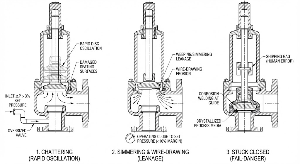
| Noisy valve chatter | Undersized valve/pulsation | Check for pump ripple, verify rating |
Valve chatter produces a distinctive rapid knocking sound. This happens when the system direct pressure hovers exactly where the valve starts to open. The solution involves either reducing system direct pressure to stay below cracking point or increasing load to push the valve fully open.
Maintenance Practices for Reliability
Systematic maintenance prevents most direct pressure valve failures. The foundation of any maintenance program starts with fluid quality management.
Best Practices Checklist
1. Filter Selection: Target a beta rating of at least 200 at 10 microns (β10≥200). This maintains ISO 4406 codes in the 17/15/12 range.
2. Gauge Accuracy: Use gauges accurate within 1% of full scale. A 3% error on a 3000 PSI system creates a 90 PSI blind spot.
3. Adjustment Procedure: Always warm the system to operating temperature before adjusting. Document the “threads exposed” to track vibration loosening.
Direct pressure hydraulic systems deliver reliable performance when components match the application and maintenance follows systematic procedures. The simplicity of direct pressure designs offers advantages, but understanding the relationship between applied force, surface area, and resulting pressure guides every decision from initial selection through troubleshooting.